Fiber Patch Cords may be small, but each one carries traffic between switches, servers, and distribution panels. Their quality affects signal continuity, troubleshooting, and day-to-day network reliability. The need for dependable links is growing. Cisco’s Annual Internet Report, published in 2020, forecast global IP traffic would reach 3.3 zettabytes annually by 2023. That figure was a forecast, not a measurement of patch-cord demand. Still, it illustrates the scale of traffic modern networks must accommodate.
A practical point from optical-communications researcher Peter Winzer’s work can be paraphrased this way: “Fiber capacity can grow as transmission technology advances.” This is a paraphrase, not a direct quotation about patch cords. Fiber links can support high bandwidth over distance, while being less affected by electromagnetic interference than copper. But the cord itself is not magic. Connector cleanliness, bend radius, correct polarity, and matching connector types all matter. One dusty end face can turn a fast link into a frustrating fault.
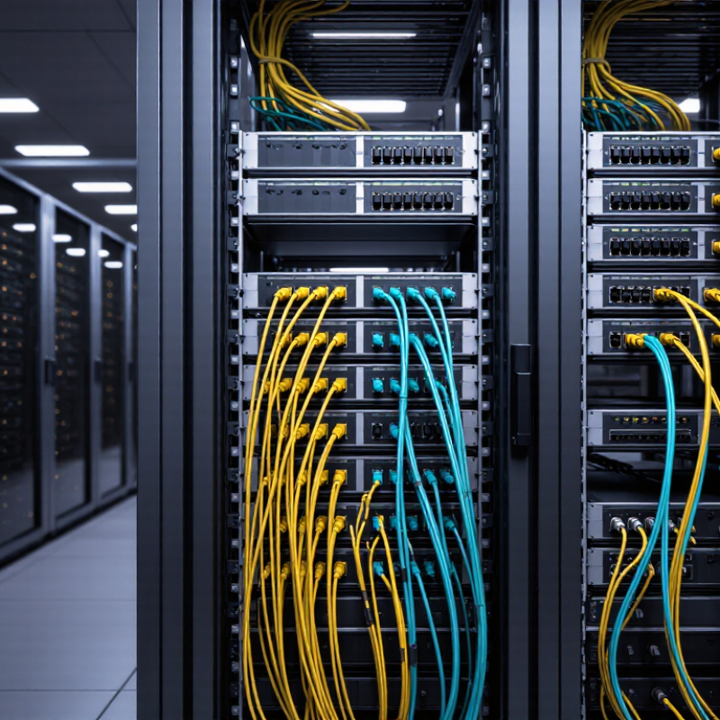
Consider a data-center rack: a short, labeled cord can make a cross-connect easier to trace during maintenance. The right choice depends on the application, reach, connector, and fiber type—not marketing claims alone. Fiber Patch Cords are valuable when they fit the link budget and installation environment. Small detail. Real consequences. A careful selection process, followed by inspection and testing, helps turn fiber’s potential into dependable network performance.
Fiber patch cords are short, pre-terminated cables that connect optical equipment, panels, and link components. Inside each cord, glass fibers carry data as light rather than electrical current. The design supports high bandwidth and reduces electromagnetic interference near power cables. ITU’s Facts and Figures 2023 reports that 5.4 billion people used the Internet worldwide. That growth increases pressure on every connection point, including small patching areas.
A reliable patch cord combines the fiber, connector, protective jacket, and strain relief. Connector types, polish quality, and fiber modes must match the network design. Single-mode fiber suits long-distance links, while multimode fiber often serves shorter data-center paths. IEC 61754 defines connector interfaces, and IEC 61300 series methods address optical performance testing. In practice, technicians should inspect end faces, clean connectors, and check insertion loss before service. Tiny dust particles can create surprisingly large signal problems.
The choice also affects maintenance. A correctly labeled cord makes port changes faster and reduces accidental disconnection. The Uptime Institute Global Data Center Survey 2024 found that 53% of respondents experienced an outage costing more than $100,000. A patch cord rarely causes the whole event alone, but weak documentation and poor handling can magnify risk. Shorter cords usually improve airflow and routing, yet overly tight bends can damage fiber. This is where my practical view remains cautious: neat-looking cabling is not automatically reliable. Test results matter more than appearance.
A fiber patch cord carries light through a glass core, not electrical current through copper. For single-mode links, the core guides light along a narrow path, helping signals travel over long distances with low loss. ITU-T Recommendation G.652 defines key properties of this fiber, including geometry, attenuation, and chromatic dispersion. Its G.652.D category supports operation around both 1310 nm and 1550 nm, common wavelengths in modern optical networks. Small details matter: a dirty connector can still weaken a carefully specified link.
G.652.D limits attenuation to 0.40 dB per kilometre at 1310 nm and 0.30 dB per kilometre at 1550 nm under specified test conditions. These figures describe the fiber, not the complete installed connection; connector loss, bends, and splices add their own effects. The International Telecommunication Union’s Facts and Figures 2023 estimated that 5.4 billion people were online, underscoring the scale of demand for dependable network infrastructure. But a standard alone cannot guarantee performance. Real measurements are needed.
When selecting patch cords, confirm that the fiber type matches the equipment and link design, then check connector polish and insertion-loss specifications. G.652 fiber is widely used, yet tight routing around a cabinet corner can cause trouble if the cord is bent too sharply. That part is easy to overlook. Standards set a reliable baseline; installation practice decides whether the light actually gets through cleanly.
Representative attenuation of G.652 single-mode fiber at common operating wavelengths
Single-mode fiber carries data as light, supporting high bandwidth over long distances. G.652 fiber has its zero-dispersion region near 1310 nm and low attenuation around 1550 nm. Values shown are representative figures, not guaranteed limits; actual performance depends on the fiber and installation.
For a 100G link inside a data center, OM4 can support 100GBASE-SR4 over distances up to 100 m. IEEE Std 802.3-2022 specifies this reach for OM4; the comparable OM3 reach is 70 m. The interface uses four transmit and four receive fibers, so an MPO-connected patch cord provides the parallel paths the link needs. Check the polarity and fiber mapping at both ends before installation. Small wiring mistakes can leave a link dark.
OM4 is designed for 850 nm multimode transmission and has a specified effective modal bandwidth of 4,700 MHz·km at that wavelength, according to TIA-492AAAD. That specification helps explain its suitability for short, high-speed links, but it does not guarantee every installed channel will reach 100 m. Connector count, cable quality, and total insertion loss matter too. Measure the actual route, including patch panels, rather than relying on a floor plan. Leave margin. In practice, that extra check can prevent a frustrating link failure; I would not treat the 100 m figure as a target to exceed.
IEEE 802.3 defines Ethernet rates up to 400 Gb/s, making fiber patch cords a practical choice for modern high-speed networks. The IEEE 802.3bs amendment specifies 200 Gb/s and 400 Gb/s Ethernet, supported by optical transmission over structured fiber systems. Copper can serve short links, but fiber offers greater bandwidth, lower attenuation, and strong resistance to electromagnetic interference.
Traffic growth makes this capacity increasingly relevant. Cisco’s Annual Internet Report (2018–2023) forecast 5.3 billion internet users and 29.3 billion connected devices by 2023. Data centers, cloud platforms, and research facilities therefore need links that can scale without frequent physical replacement. A properly selected fiber patch cord helps maintain signal integrity between switches, transceivers, and patch panels.
Small details matter. Keep connectors capped, inspect end faces, and respect the specified bend radius. One dirty connector can weaken a high-speed link. Fiber is not automatically better in every installation; distance, transceiver type, polarity, and maintenance skills still influence performance. That is easy to overlook. The IEEE standard defines the transmission rate, but it does not remove poor installation practices. In real deployments, a clean, correctly matched patch cord often matters more than a theoretical headline speed.
| Ethernet Rate | Representative IEEE 802.3 Ethernet Type | Typical Fiber Medium | Common Wavelength | Representative Maximum Link Reach | Typical Network Use | Why Fiber Patch Cords Fit |
|---|---|---|---|---|---|---|
| 1 Gb/s | 1000BASE-SX | Multimode fiber OM1, OM2, OM3, or OM4 |
850 nm | Up to 275 m on OM1 Up to 550 m on OM2 or higher, depending on the link design |
Access-layer switches, server connections, and campus distribution links | Provides low-latency optical connectivity and supports longer distances than copper in many structured-cabling environments. |
| 10 Gb/s | 10GBASE-SR | Multimode fiber OM3, OM4, or OM5 |
850 nm | Up to 300 m on OM3 Up to 400 m on OM4 or OM5 |
Data-center server-to-switch and switch-to-switch connections | High-bandwidth multimode patching supports short-reach data-center links with compact, lightweight cabling. |
| 25 Gb/s | 25GBASE-SR | Multimode fiber OM3, OM4, or OM5 |
850 nm | Typically up to 70 m on OM3 Up to 100 m on OM4 or OM5 |
High-density server access and modern data-center leaf connections | Fiber patch cords help deliver higher port bandwidth without the size and electromagnetic limitations associated with copper cabling. |
| 40 Gb/s | 40GBASE-SR4 | Four-lane multimode fiber OM3 or OM4 |
850 nm | Up to 100 m on OM3 Up to 150 m on OM4 |
Data-center aggregation and short-reach switch interconnects | Parallel-fiber patching carries multiple optical lanes while maintaining a relatively small cable footprint. |
| 100 Gb/s | 100GBASE-SR4 | Four-lane multimode fiber OM3, OM4, or OM5 |
850 nm | Up to 70 m on OM3 Up to 100 m on OM4 or OM5 |
Leaf-spine uplinks, aggregation, and high-performance computing clusters | Optical patch cords support parallel transmission, high port density, and consistent performance when connector cleanliness and polarity are controlled. |
| 100 Gb/s | 100GBASE-LR4 | Single-mode fiber | 1310 nm, using multiple optical lanes | Up to 10 km | Campus backbones, data-center interconnects, and metropolitan links | Single-mode patch cords provide the low-loss optical path required for extended-distance, high-speed Ethernet links. |
| 400 Gb/s | 400GBASE-SR8 | Eight-lane multimode fiber OM4 or OM5 |
850 nm | Up to 100 m on OM4 or OM5 | High-capacity data-center spine and switch-to-switch connections | Multifiber patch cords support parallel optical lanes needed for very high aggregate Ethernet rates in short-reach environments. |
| 400 Gb/s | 400GBASE-FR8 | Single-mode fiber | 1310 nm, using multiple optical lanes | Up to 2 km | Data-center interconnects and medium-distance backbone links | Single-mode fiber patching combines high capacity with extended reach, making it suitable for inter-building and large-facility links. |
| Fiber patch cords are suitable for fast Ethernet networks because optical fiber offers high bandwidth, low electromagnetic susceptibility, low signal attenuation, and flexible support for both multimode short-reach links and single-mode extended-reach links. Actual reach depends on the complete channel design, transceiver type, fiber grade, connector performance, polarity, and installation quality. | ||||||
IEC 61754 defines connector interface families, not a universal “plug-and-play” guarantee. For example, IEC 61754-4 covers SC connectors, IEC 61754-20 covers LC connectors, and IEC 61754-7 covers MPO connectors. Match the cord’s connector type, fiber mode, and polish to the equipment and adapter. An LC plug may look compatible at a glance, yet an incorrect polish or mode can raise loss or cause a link failure.
Polarity determines whether each transmitter reaches the intended receiver. For duplex links, document the chosen polarity method at both ends; common methods are described in TIA-568.3-D, not IEC 61754. Label cords “A-to-B” or “A-to-A” only when those labels reflect the actual path. Small details matter. Keep bend radii within the cord manufacturer’s specification, and avoid tight ties that flatten the jacket. Clean, then inspect. Dust on an end face can undermine an otherwise correct connection, so inspect and clean both ends before mating.
Demand makes these checks practical, not merely procedural. Cisco’s Annual Internet Report (2018–2023) projected 29.3 billion networked devices worldwide by 2023, increasing pressure on reliable links. That forecast is not a measurement of fiber-cord failures, but it illustrates the scale of connected infrastructure. Record connector type, polarity, and route during installation; later technicians should not have to guess. Even experienced crews can mislabel a patch cord, especially when both ends appear identical. A simple continuity check can catch that mistake.
It carries light through a glass core. Single-mode fiber guides light along a very narrow path.
It defines fiber geometry, attenuation, and chromatic dispersion. These details create a dependable technical baseline.
G.652.D supports operation around 1310 nm and 1550 nm. These wavelengths suit many modern optical networks.
The limit is 0.40 dB per kilometre at 1310 nm. At 1550 nm, it is 0.30 dB per kilometre.
No. They describe the fiber under test conditions. Connectors, bends, and splices add separate losses.
A dirty connector, sharp bend, or mismatched transceiver can weaken the signal. The standard cannot fix careless installation.
Match the fiber type with the equipment and link design. Check connector polish, insertion loss, polarity, and bend radius.
Fiber offers high bandwidth, low attenuation, and strong resistance to electromagnetic interference. It can support rates up to 400 Gb/s in suitable systems.
Keep connectors capped and inspect end faces before connection. Route cords gently around cabinets. Small details matter.
Not necessarily. Clean connectors and correct matching may matter more than a headline speed. This is easy to overlook.
Fiber Patch Cords are essential link components that connect optical equipment, panels, and network devices through optical fibers and precision connectors. They transmit data as light, providing high bandwidth, low signal loss, and strong resistance to electromagnetic interference. Single-mode fiber specifications defined by ITU-T G.652 support long-distance, high-performance communication, while multimode options such as OM4 are well suited to data center links, including 100GBASE-SR4 connections up to 100 meters.
As Ethernet technology continues to advance toward rates of 400 Gb/s, selecting the correct fiber type, connector, and transmission distance is increasingly important. IEC 61754 connector standards help ensure compatibility and reliable physical connections, while correct polarity supports accurate signal transmission. Proper handling also matters: avoid excessive bending, protect end faces from dust, and inspect connectors before installation. By combining suitable specifications with careful installation practices, Fiber Patch Cords can provide stable, scalable, and efficient network performance.

KOCENT OPTEC