How to Choose the Right LC FC Fiber Patch Cord?

Time:2026-10-24 Author:Isabella
0%

Choosing the right Lc Fc Fiber Patch Cord is not a cosmetic decision. It affects signal stability, installation time, and future maintenance. Cisco’s Annual Internet Report projected 29.3 billion networked devices and 396.1 exabytes of monthly IP traffic by 2023. That scale makes small optical losses increasingly expensive.

The connector must match the equipment and the installation environment. LC connectors suit dense patch panels because their compact latch saves rack space. FC connectors use a threaded coupling, making them valuable where vibration resistance and secure alignment matter. IEC 61754-20 defines the LC interface, while IEC 61754-13 covers the FC interface. The cable type also matters. OS2 supports long-distance single-mode links; OM3 and OM4 support high-speed multimode links over shorter distances. UPC and APC end faces are not interchangeable in every system. That sounds obvious. It is not.

Jim Hayes, founder of the Fiber Optic Association, states, “The only way to know if a fiber optic cable plant is good is to test it.” His point should guide every selection. Check insertion loss, return loss, polarity, jacket rating, bend radius, and ferrule cleanliness. The FOA Reference Guide to Fiber Optics repeatedly emphasizes inspection, cleaning, and testing before connection. A polished connector can still fail under dust. A low-cost cord can become expensive after repeated replacement. This guide examines those practical trade-offs, including standards, data-sheet claims, and real installation conditions. Some recommendations will remain application-dependent. That is the honest limitation. Certified test results should outrank attractive packaging.
How to Choose the Right LC FC Fiber Patch Cord?

Define LC FC Fiber Patch Cords and Their Main Applications

An LC FC fiber patch cord is a duplex or simplex optical cable with an LC connector on one end and an FC connector on the other. LC connectors use a compact latch, while FC connectors use a threaded coupling sleeve. The interface requirements are defined in IEC 61754-20 for LC and IEC 61754-13 for FC connectors. They are not interchangeable.

These cords are useful when equipment uses different connector systems. Common applications include telecommunications cabinets, optical distribution frames, laboratory test equipment, industrial networks, and older access systems. In a rack, the smaller LC side saves panel space. The FC side offers firm retention during vibration and repeated testing. The International Telecommunication Union reported about 5.5 billion Internet users in 2024, increasing pressure on reliable fiber infrastructure. Small connection errors can still create large service problems.

Selection should match the fiber mode, polish type, cable length, jacket rating, insertion loss, and return loss. Single-mode cords often serve long-distance links, while multimode cords support shorter data-center connections. APC and UPC ends should never be mixed casually. A technician should also inspect end faces before installation; dust can imitate a faulty transceiver. IEC standards define interface dimensions, but field conditions are less perfect. Labels may be incomplete. Records may be outdated. That is why testing the installed link remains safer than trusting the package description alone.

Compare LC and FC Connector Designs and Compatibility

How to Choose the Right LC FC Fiber Patch Cord?

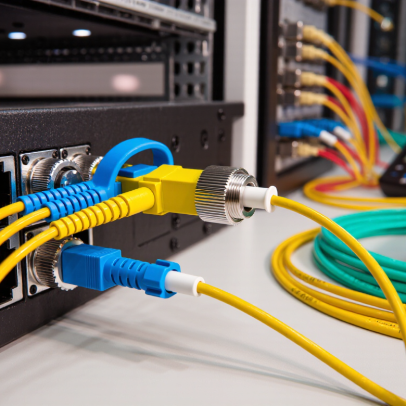
Choosing between LC and FC fiber patch cords starts with the equipment, not the cable color. LC connectors use a compact latch mechanism and fit densely packed switches, panels, and transceivers. FC connectors use a threaded sleeve, which offers firm retention in environments with vibration. They take more space.

Check the connector interface on both devices. An LC plug will not fit an FC adapter without the correct hybrid connection. Confirm single-mode or multimode fiber before ordering. Also match the polish type, such as UPC with UPC or APC with APC. Mixing polish angles can create excessive insertion loss and unstable links. I have seen a connector appear fully seated while its key was slightly misaligned. The link worked, but the power reading was poor.

Inspect the patch panel layout and cable route. LC duplex cords can simplify polarity management, while FC cords may suit test instruments or older communication hardware. Measure the required length carefully. Extra cable often forms tight coils behind the rack, increasing bend risk. Keep the bend radius within the cable specification. Clean both ferrules before connection, even when they look spotless. Dust is small but costly. One detail is easy to overlook: connector gender and adapter type. A final inspection should verify latch engagement, thread alignment, polarity, end-face cleanliness, and measured optical loss. I would not rely on a visual fit alone. Real compatibility requires stable performance under actual installation conditions.

Select the Correct Fiber Type, Mode, and Core Size

How to Choose the Right LC FC Fiber Patch Cord?

Selecting the correct fiber type begins with the equipment and transmission distance. Single-mode fiber, usually 9/125 µm, suits long-distance links and higher-speed campus connections. Multimode fiber, commonly 50/125 µm, works well inside data centers and shorter building runs. OM3 and OM4 support high-bandwidth applications, while older 62.5/125 µm fiber may still appear in existing networks.

Mode and core size must match on both ends. A single-mode transceiver should not connect to a multimode patch cord. The link may show light, yet performance can remain unstable. Check the transceiver label, cable jacket markings, and network documentation before ordering. Core size sounds like a small detail, but a mismatch can create excessive loss and confusing test results.

Connector selection also matters. LC connectors save rack space, while FC connectors use a threaded coupling that resists accidental movement. Confirm the equipment ports, connector polish, and fiber mode together. UPC and APC ends are not interchangeable in every system, especially where return loss matters. In field installations, I have seen correct-looking cords fail because one connector was APC and the port required UPC. Labels can be incomplete, so an optical test is worth performing when specifications are unclear.

Match Cable Performance to Distance, Speed, and Network Needs

How to Choose the Right LC FC Fiber Patch Cord?

Match Cable Performance to Distance, Speed, and Network Needs

When selecting an LC FC fiber patch cord, begin with the link’s distance and transceiver specification. Connector shape alone does not determine performance. LC connectors suit dense panels, while threaded FC connectors resist movement in vibration-prone areas. Use the connector required at each end.

For short data-center links, multimode fiber can provide practical high-speed service. OM3 and OM4 commonly support 850 nm transmission, but distance changes with speed and optics. Single-mode OS2 is usually better for longer campus or building links. It commonly operates at 1310 or 1550 nm. Check the optical budget, not just the advertised reach. Excessive insertion loss can weaken an otherwise healthy link. A small loss still matters.

Field checks matter. Inspect and clean both end faces before connection. Confirm UPC or APC polish compatibility. Never force a mismatched interface. Choose duplex polarity, jacket rating, and length carefully. A three-meter cord routed through a crowded rack may bend sharply. I have seen extra slack become a real fault source. Shorter is not always better. A power meter and light source can verify actual performance. Record the result before closing the rack. Yet measurements can expose poor installation, not only poor cable selection.

Verify Polishing, Jacket, Length, and Installation Requirements

How to Choose the Right LC FC Fiber Patch Cord?

Network demand makes small cabling decisions more important. Cisco’s Annual Internet Report projected 396 exabytes of global IP traffic monthly in 2022. A poorly selected patch cord can add loss, reflection, or installation stress.

Start by verifying the polishing type. UPC suits many standard data links, while APC reduces reflected power in sensitive systems. Never mix APC and UPC connectors. Inspect every endface under IEC 61300-3-35 guidelines before connection. A clean connector matters more than an impressive specification sheet. I have seen new cords fail because installers skipped this simple check.

Measure the real route, including slack and service loops. Extra length prevents tension, but excessive slack creates messy bends. Follow the manufacturer’s minimum bend radius. Check whether the jacket meets the site’s requirements, such as LSZH, flame rating, outdoor resistance, or tight rack spacing. Confirm LC and FC keying, polarity, ferrule compatibility, and insertion-loss limits under IEC 61755 or the applicable cabling standard. Do not assume every FC cord fits every adapter. It is an easy mistake.

Installation quality still decides performance. Clean, inspect, connect, and test. A light source and power meter can verify link loss more reliably than visual confidence. The practical weakness is often human handling, not fiber design.

FAQS

What is an LC FC fiber patch cord?

It is an optical cable with an LC connector on one end and an FC connector on the other. The LC side uses a compact latch. The FC side uses a threaded sleeve. They are not directly interchangeable.

Where are LC FC patch cords commonly used?

They connect equipment using different connector systems. Typical locations include telecom cabinets, distribution frames, laboratories, industrial networks, and older access systems. LC saves panel space. FC holds firmly during vibration and repeated testing.

How do LC and FC connectors differ?

LC connectors are small and suit dense racks, switches, and transceivers. FC connectors need more space but resist accidental movement. Their locking methods differ. Neither connector fits the other without a suitable adapter or hybrid cord.

How should I choose single-mode or multimode fiber?

Choose single-mode fiber for long-distance links and higher-speed campus connections. Choose multimode fiber for shorter building or data-center runs. Common multimode sizes include 50/125 micrometers and older 62.5/125 micrometers. Check the equipment labels before ordering.

Can I connect single-mode equipment to multimode fiber?

Avoid this combination. The link may show light but still perform poorly or become unstable. Match the transceiver, cable mode, and core size on both ends. A quick optical test can expose a hidden mismatch.

Should UPC and APC connectors be mixed?

No. Match the polish type on the connector and equipment port. Mixing angles can increase insertion loss and reduce link stability. A connector may look correct while producing weak power readings.

What should I inspect before installing the cord?

Check connector type, gender, adapter type, polarity, latch engagement, and thread alignment. Inspect both end faces for dust. Clean them before connection, even when they look spotless. Dust matters. A dirty ferrule can imitate a faulty transceiver.

How can I prevent installation problems?

Measure the needed length carefully and avoid tight coils behind the rack. Keep the bend radius within the cable specification. Test the installed link instead of trusting the package description alone. Labels may be incomplete. Records may also be outdated. I would recheck everything.

Conclusion

Choosing the right Lc Fc Fiber Patch Cord requires more than matching connector names. These patch cords are used to connect fiber equipment, panels, transceivers, and network devices in data centers, telecommunications systems, and other high-speed communication environments. LC connectors are compact and suitable for high-density installations, while FC connectors use a threaded coupling design that provides strong connection stability in environments subject to vibration. Before purchasing, confirm that both connector types are compatible with the equipment and adapter interfaces.

You should also select the correct fiber mode and core size, such as single-mode or multimode, according to the transmission distance and network design. Match the cable’s performance with required speed, bandwidth, and link length, then verify the polishing type, jacket material, cable length, and installation conditions. A careful review of these factors helps ensure reliable signal transmission, easy deployment, and long-term network performance.

Isabella

Isabella

Isabella is a dedicated marketing professional with a sharp focus on driving brand growth and engagement through strategic content creation. With an extensive background in digital marketing, she combines her passion for storytelling with her keen understanding of industry trends to deliver......