Choosing the right Fiber Optic Splitter Box affects signal stability, installation time, and long-term maintenance. It is not merely a protective enclosure. It organizes splitters, manages fiber slack, and shields delicate connections from dust, moisture, and accidental pulling. In a busy telecommunications cabinet, a poorly selected box can create crowded trays, sharp bends, and confusing cable routes. These small problems often become expensive service calls later.
A practical choice begins with the network’s actual requirements. Consider splitter type, input and output counts, connector compatibility, fiber bend radius, and available installation space. Outdoor projects also require suitable sealing, UV resistance, and protection against temperature changes. Experienced installers usually inspect cable entry methods and closure quality before comparing appearance or price. Check the details carefully. A compact box may save space, yet leave insufficient room for future expansion. A larger model may improve access, but waste valuable cabinet capacity. There is no universal solution.
Reliable manufacturers should provide clear specifications, test information, installation guidance, and traceable quality standards. However, published data does not replace field judgment. Before ordering, measure the mounting surface and estimate the number of fusion splices, adapters, and reserve fibers. Also consider whether technicians can open the enclosure without disturbing active connections. That detail is easy to overlook. The best Fiber Optic Splitter Box balances protection, capacity, accessibility, and total ownership cost. Even careful planning can miss something, so reviewing the design with an experienced fiber technician remains worthwhile.
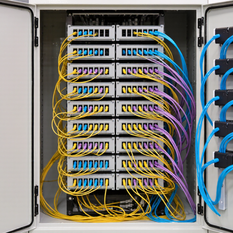
When choosing a fiber optic splitter box, identify the fiber and splitter technology before comparing enclosure designs. For most FTTH deployments, single-mode G.657 fiber is a practical choice. Its bend-insensitive construction tolerates tighter routing near closures, cabinets, and subscriber outlets. This matters when installation space is limited. However, G.657 does not remove the need to respect the specified bend radius. Excessive bending can still increase attenuation and weaken long-term reliability.
The splitter should usually use PLC technology when one optical input must serve multiple subscribers evenly. A PLC splitter provides consistent splitting across its output ports and supports common ratios, such as 1:8, 1:16, or 1:32. Check the total insertion loss, operating wavelength, and uniformity between ports. These details affect optical budgets more than the box appearance. Match the splitter connectors and adapters with the distribution cables. A mismatch can create unnecessary connection loss.
Inspect the box’s sealing, splice capacity, cable entry points, and grounding provisions. In outdoor locations, dust and moisture protection deserve close attention. I have seen installations fail because technicians focused on port count while ignoring cable management. That choice looked efficient at first. It was not. Leave enough room for splice trays, bend control, labels, and future testing. Before acceptance, measure insertion loss and return loss with calibrated equipment. Do not rely only on factory figures. Field conditions can change the result.
Single-mode G.657 fiber suits many FTTH installations. Its bend-insensitive design helps in tight cabinets and wall outlets. Respect the bend radius.
PLC technology divides one optical input evenly across multiple outputs. Common ratios include 1:8, 1:16, and 1:32. Check insertion loss and port uniformity.
Verify the splitting ratio, operating wavelength, total insertion loss, and output uniformity. Match connectors and adapters with distribution cables. Mismatch creates avoidable loss.
Count incoming fibers, splitter pigtails, spare fibers, and planned future connections. Leave space for splice trays, labels, and controlled fiber slack. Crowded trays cause trouble later.
Confirm the connector type, adapter design, and polish style. SC/APC connectors can reduce back reflection in many single-mode access networks. Do not assume compatibility.
IP65 protection helps block dust and low-pressure water jets in outdoor or damp areas. Check seals, cable glands, and cover alignment. A damaged gasket changes everything.
Request test reports covering insertion loss, return loss, uniformity, and operating wavelengths. Also review temperature, humidity, vibration, and impact testing. A certificate alone is weak.
Ask for sample numbers, test dates, configurations, and acceptance limits. Measure insertion loss and return loss after installation with calibrated equipment. Field conditions can disagree.
No. A larger box offers more working room but may waste wall space and raise installation costs. Bigger is not automatically better.
Technicians may focus on port count and overlook bend control, cable movement, grounding, or entry-point stress. I would question that habit. Appearance is not performance.
Choosing the right Fiber Optic Splitter Box is essential for building a reliable and easy-to-maintain fiber distribution system. Start by confirming that it supports single-mode G.657 fiber and PLC splitter technology, then select a split ratio that matches the network’s capacity and user requirements. Options such as 1×8, 1×16, and 1×32 provide different distribution capabilities, but higher split ratios also create greater insertion loss. For example, a 1×32 PLC splitter typically adds approximately 17 dB, so the total optical budget should be checked carefully.
The box design should also suit installation and maintenance needs. SC/APC adapters, sufficient splicing capacity, organized cable routing, and IP65 protection can improve connection stability and environmental resistance. Finally, verify that the product has been tested according to relevant requirements, including IEC 61753 and Telcordia GR-326. Considering fiber type, split ratio, optical loss, enclosure protection, and compliance together helps ensure dependable long-term performance.

 KOCENT OPTEC