Global fiber infrastructure is entering another demanding upgrade cycle. Cloud expansion, AI clusters, and 5G transport are increasing pressure on high-density optical distribution. Dell’Oro Group’s data center research continues to identify strong investment in cloud and data center infrastructure. The International Data Corporation also reports sustained growth in cloud-related infrastructure spending. These trends make the Lc Duplex Patch Panel more than a passive rack accessory. It becomes a practical control point for capacity, polarity, maintenance, and future expansion.
Small details matter. A reliable panel should support standard LC duplex adapters, clear port numbering, secure fiber management, and controlled bend radius. TIA-568.3-E and IEC 61754-20 provide useful references for optical cabling and LC connector interfaces. The Fiber Optic Association also emphasizes inspection, cleaning, polarity testing, and insertion-loss measurement before acceptance. Those steps sound basic. They prevent expensive troubleshooting later.
Global buyers also need evidence beyond attractive specifications. Our comparison considers rack compatibility, adapter quality, splice or patching options, labeling space, cable access, and environmental durability. Corning’s industry guidance and CommScope’s structured cabling documentation show why connector cleanliness and fiber routing directly affect network performance. Still, “best” depends on the installation. A compact panel may fit a small cabinet but frustrate technicians during expansion. A highly dense design may save rack space but reduce working room. This article evaluates leading 2026 options with that compromise in mind, using documented standards, manufacturer information, and realistic deployment concerns. Some product claims remain difficult to verify without independent testing. That limitation deserves attention.
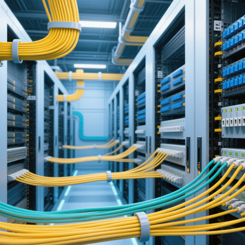
An LC duplex patch panel organizes two fiber connections in one compact adapter. The two LC ports usually carry transmit and receive signals. Their small latch makes dense rack layouts practical. Inside, adapters align ceramic ferrules with precision sleeves. A fiber patch cord plugs into each side, creating a controlled connection between equipment and backbone cabling. The panel itself does not amplify data. It provides protection, alignment, and easier maintenance.
During installation, technicians mount the panel in a rack or wall enclosure. They route fibers through guides, preserve bend radius, and label every duplex pair. A visual fault locator can reveal breaks or poor seating.
An optical loss test confirms whether the link meets its design limit. Small dust particles matter. One dirty connector can weaken a stable-looking circuit.
I have seen neat panels fail because polarity labels were unclear. That detail deserves more attention than it receives.
Tips:
A panel may fit physically yet still create compatibility problems. That is an easy mistake, especially when buying across regions. Review the datasheet, inspect the port layout, and ask for test records when reliability matters.
A dependable LC duplex patch panel starts with optical performance, not port count. The OECD Broadband Portal reported fiber at about 43% of fixed broadband subscriptions in December 2023. That share increases pressure on every connector interface. Choose panels with documented insertion loss and return loss, tested under IEC 61300 procedures. A low-loss target near 0.35 dB per connection is practical. Still, test conditions can differ.
Fiber compatibility matters across borders. Confirm single-mode or multimode support before ordering. For single-mode networks, OS2 performance suits longer links and higher transmission demands. The adapter should comply with IEC 61754-20 geometry requirements for LC interfaces. Polarity must remain clear through duplex clips, cassettes, and trunk cables. Small mistakes here can reverse transmit and receive paths. It happens more often than specifications suggest.
Mechanical details also deserve attention. Check rack units, port density, labeling space, bend-radius control, and cable-entry direction. The ITU reported 5.4 billion people online in 2023, increasing the need for scalable infrastructure. A panel should tolerate repeated patching without damaging ceramic sleeves or latches. Verify operating temperature, humidity, flame rating, and salt-mist requirements for regional sites. I would not trust a datasheet alone. Request sample testing, inspection records, and end-face cleanliness results. The perfect panel rarely exists; the better choice is the one whose limitations are visible.
2026 Best LC Duplex Patch Panel for Global Buyers?
How to Compare the Best LC Duplex Patch Panels in 2026
Choosing an LC duplex patch panel requires more than counting ports. Each duplex adapter serves two fibers, so density can rise quickly inside a crowded rack. Measure available rack space, cable entry angles, and rear working clearance before comparing prices. A compact panel is not always practical. Small details matter.
Professional buyers should check connector alignment, adapter retention, polarity options, and compatible fiber types. For reliable transmission, review insertion loss and return loss data from controlled test conditions. Compliance with relevant IEC connector standards and structured cabling requirements also improves confidence. Ask for test reports, material specifications, and traceable quality records. Records matter.
Installation experience often reveals overlooked issues. Sharp cable bends, weak strain relief, or unclear labels can create faults months later. Look for a suitable bend-radius guide, secure splice management, and front-access labeling. Metal construction may improve durability, but poor coating can still lead to corrosion in humid rooms. I have seen attractive panels become difficult to service because the rear tray was too shallow. This is where comparisons become less certain. Published specifications may not reflect crowded cabinets, repeated reconnections, or rushed maintenance. A careful buyer should inspect samples, verify polarity, and test a loaded panel before approving a large deployment.
| Comparison Dimension | Compact 12-Port Panel | Standard 24-Port Panel | High-Density 48-Port Panel | What Global Buyers Should Check |
|---|---|---|---|---|
| LC Duplex Adapter Capacity | 12 LC duplex adapters Up to 24 fibers |
24 LC duplex adapters Up to 48 fibers |
48 LC duplex adapters Up to 96 fibers |
Confirm whether the stated port count refers to duplex ports or individual fiber positions. |
| Rack-Mount Size | Typically 1U | Typically 1U | Typically 1U or 2U | Verify the rack width, mounting-hole pattern, and available clearance behind the panel. |
| Common Rack Width | 19-inch rack compatibility | 19-inch rack compatibility | 19-inch rack compatibility | A removable mounting ear or adjustable bracket can simplify installation in different cabinets. |
| Connector Type | LC duplex, UPC or APC options | LC duplex, UPC or APC options | LC duplex, UPC or APC options | Do not mix UPC and APC connector interfaces in the same optical link. |
| Fiber Compatibility | Usually single-mode and multimode versions available | Usually single-mode and multimode versions available | Usually single-mode and multimode versions available | Match the adapter and pigtail specification to OS2, OM3, OM4, or another required fiber category. |
| Typical Insertion Loss Target | ≤ 0.50 dB per mated pair | ≤ 0.50 dB per mated pair | ≤ 0.50 dB per mated pair | Lower measured loss is preferable; request test conditions and wavelength data before approval. |
| Typical Return Loss Target | UPC: ≥ 50 dB APC: ≥ 55 dB |
UPC: ≥ 50 dB APC: ≥ 55 dB |
Use the return-loss requirement of the active equipment and optical network design. |
| Fiber Management | Basic routing area and splice tray space | Dedicated routing area with improved cable organization | Expanded routing and splice-management capacity recommended | Check bend-radius control, cable tie points, splice protection, and front-access requirements. |
| Minimum Fiber Bend Radius | Follow the connected cable specification; 30 mm is a common protected routing target | Follow the connected cable specification; 30 mm is a common protected routing target | Follow the connected cable specification; larger routing space is preferred | The cable manufacturer’s bend-radius requirement takes priority over a generic panel value. |
| Housing Material | Powder-coated steel or aluminum | Powder-coated steel or aluminum | Powder-coated steel is common for high-density installations | Evaluate corrosion protection, grounding provision, mechanical strength, and enclosure finish. |
| Operating Temperature | Common target: −20°C to +70°C | Common target: −20°C to +70°C | Common target: −20°C to +70°C | Confirm the tested range for the intended data center, telecom room, or outdoor cabinet. |
| Standards to Review | IEC 61754-20, IEC 61300 test methods, TIA-568 practices | IEC 61754-20, IEC 61300 test methods, TIA-568 practices | IEC 61754-20, IEC 61300 test methods, TIA-568 practices | Request a conformity statement and product test report suitable for the destination market. |
| Best Use Case | Small server rooms, access networks, and low-density links | General data-center distribution and enterprise backbone connections | High-density data centers and telecom distribution frames | Select capacity based on current ports plus planned expansion, not only the lowest purchase price. |
| Procurement Documents | Dimension drawing, material details, optical test data | Dimension drawing, material details, optical test data | Dimension drawing, material details, optical test data, packing information | For global shipments, also confirm HS classification, packaging protection, labeling, and installation instructions. |
Note: The optical performance values shown are common specification targets for LC duplex patch-panel assemblies. Actual limits vary by adapter type, fiber category, wavelength, test method, and project requirements.
Choosing an LC duplex patch panel requires more than checking port density. Confirm whether the network uses single-mode OS2 or multimode OM3 or OM4 fiber. The panel, adapters, pigtails, and patch cords must match the same fiber type. Check the connector polish, usually UPC or APC, before ordering. Mixing these options can increase insertion loss or cause unstable links. Verify rack width, mounting depth, and cable-entry direction. A panel that fits the rack may still leave too little room for bend protection.
Tips: Check polarity labels, adapter alignment, splice-tray capacity, and the minimum bend radius. Leave service loops, but do not coil fiber tightly. Use clear labels on both ends. Test every finished link with an optical loss test set. OTDR testing can reveal hidden reflections, bad splices, or excessive bends.
Environmental details also matter for global installations. Confirm operating temperature, humidity limits, flame ratings, and applicable regional compliance documents. Inspect the locking hardware and grounding design where metallic parts are used. Field experience shows that poor cable management causes more trouble than the panel itself. A tidy enclosure can still hide a sharp bend. I have also seen buyers focus on port count and overlook future expansion. That choice saves space today, but it may force disruptive replacement later. Compatibility is not only physical. It includes fiber performance, maintenance access, documentation, and testing discipline.
Choosing the 2026 best LC duplex patch panel starts with measurable evidence, not attractive product photos. Global buyers should verify LC connector compatibility against the latest applicable IEC 61754-20, ISO/IEC, and TIA standards. Ask for the exact edition. Standards change.
A reliable evaluation includes insertion loss, return loss, polarity, port density, and adapter alignment. Request test results from calibrated equipment, not only a general compliance statement. Check whether the panel supports the required fiber type, bend radius, and cable diameter.
Inspect the metal frame, labeling, splice management, and grounding points. Small details matter during installation. Poor labels create expensive mistakes.
Supplier assessment needs equal attention. Review production records, material traceability, inspection procedures, and sample consistency. A factory audit or live video inspection can reveal packaging weaknesses and careless assembly. Confirm flame-retardant materials, export documents, warranty terms, and replacement procedures for damaged units.
Ask how the supplier handles revisions. A polished datasheet is not proof. Samples can also hide variation between batches. I would test several units from different cartons, because one perfect sample may create false confidence.
Price deserves attention, but stable performance, documented testing, and responsive technical support usually protect the total project cost better. Suppliers should answer technical questions clearly and provide records that another engineer can verify.
It organizes two fiber connections within one compact adapter. One port carries transmission. The other usually carries reception. It protects connectors and simplifies maintenance.
Ceramic ferrules align inside precision sleeves. Patch cords connect equipment with backbone cabling. The panel maintains alignment between both sides. It does not amplify optical signals.
Technicians can mount it inside a rack or wall enclosure. Cable guides should protect the fiber bend radius. Leave service loops for future repairs. The layout should remain easy to inspect.
Check fiber mode, connector polish, rack size, and adapter type. Review insertion loss and return loss. Confirm cable diameter and port density. A physical fit does not guarantee compatibility.
Duplex polarity keeps transmit and receive paths correctly matched. Unclear labels can reverse the connection. Each pair should have a visible identifier. Small mistakes become costly.
Request test results from calibrated equipment. Check alignment, loss values, bend-radius control, and material records. Inspect several units from different cartons. One perfect sample proves little.
Keep unused ports capped. Clean connectors with approved tools, never clothing. Use a visual fault locator for breaks or poor seating. Optical loss testing confirms link performance.
Review production records, inspection procedures, and material traceability. Ask about damaged-unit replacement and document revisions. A live inspection may reveal weak packaging or careless assembly. Price matters, but stable performance matters more.
Choosing the right Lc Duplex Patch Panel in 2026 requires more than comparing prices. Buyers should understand how duplex adapters organize and connect two fiber strands, supporting efficient signal transmission, easy circuit management, and reliable maintenance. Important specifications include fiber type, connector performance, insertion and return loss, port density, housing design, cable management, and compatibility with existing racks, cassettes, and transceivers. The best option should match the network’s capacity, environmental conditions, and future expansion plans.
During installation, global buyers should verify mounting dimensions, polarity, labeling, bend-radius protection, and access for testing or upgrades. Quality evaluation should include material durability, consistent manufacturing, inspection records, packaging protection, and compliance with relevant international optical and safety standards. Buyers should also assess supplier communication, customization capability, sample verification, production consistency, lead time, and after-sales support. A careful comparison of technical performance, compatibility, quality control, and supply reliability can help organizations select a dependable patch panel for long-term fiber network operation.

KOCENT OPTEC